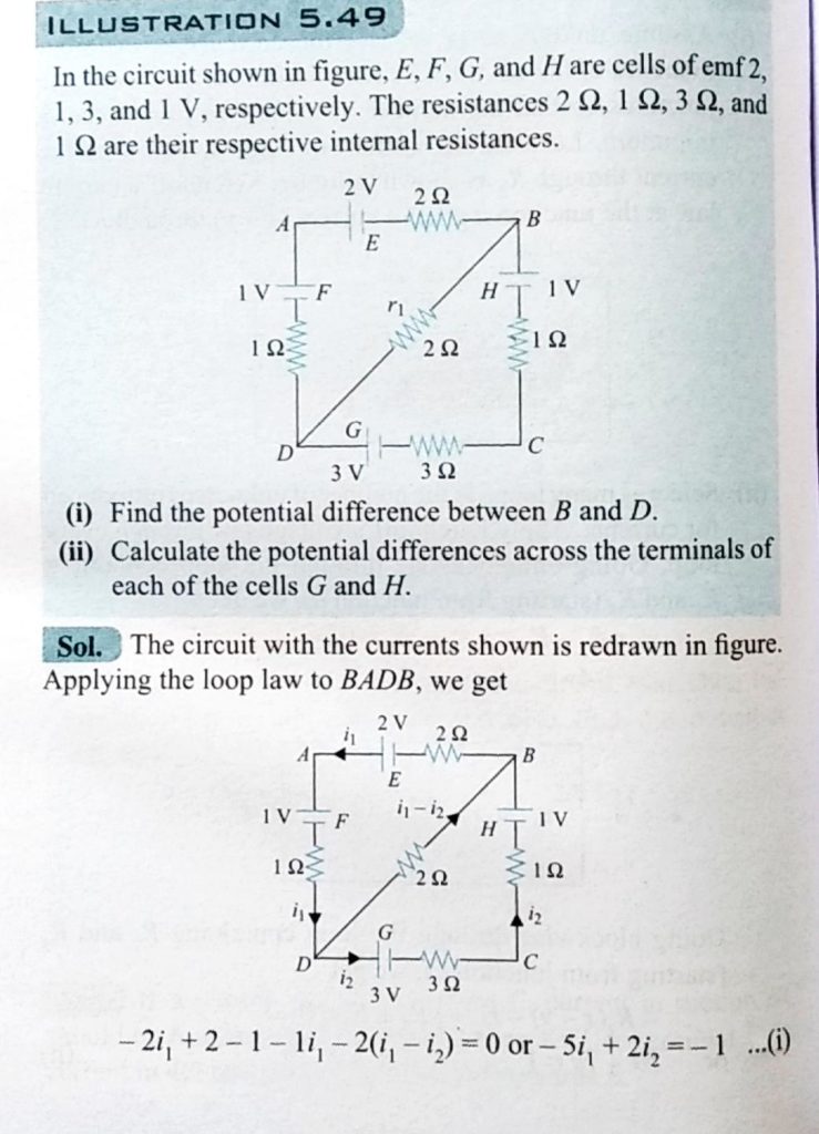
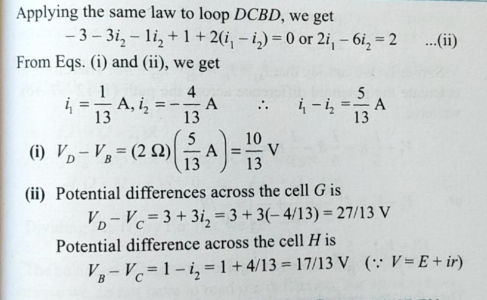
In the circuit shown in figure E,F, G and H are cell of emf 2,1,3, and 1V respectively. The resistances 2,1,3 and 1(Omega)are their respective internal resistance .Calculate (a)the potential difference between B and D and (b) the potential differences across the terminals of each of each of the cells G and H.