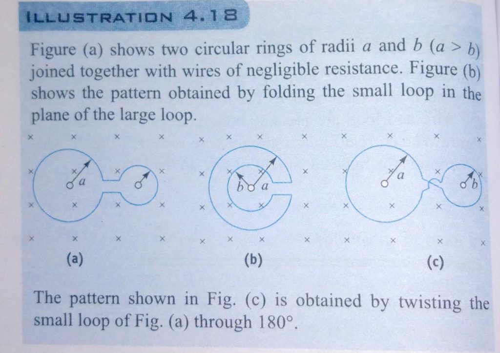
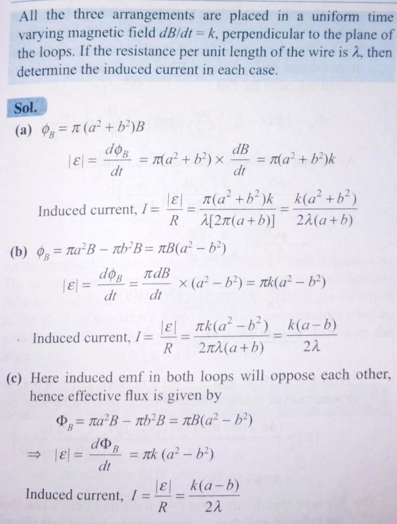
Figure (a) shown two circular rings of radii a and b (a>b) joined together with wires of negligible resistance. Figure 3.15(b) shown thew pattern obtained by folding the small loop in the plane of the large loop. The pattern shown in Fig.3.15( c ) is obtained by twisting the small loop of Fig.3.15(a) through 180∘. All the three arrangement are placed in a uniform time varying magnetic field dB/dt=k, perpendicular to the plane of the loops. if the resistance per unit length of the wire is λ, then determine the induced current in each case.